
English
English
Views: 0 Author: Site Editor Publish Time: 2026-05-20 Origin: Site


Replacing a vision sensor in specialized hardware rarely functions as a simple plug-and-play operation. Whether you upgrade to higher resolutions or swap out a degraded sensor, the procedure demands absolute precision. You must adhere to strict hardware protocols. You also need to follow electrostatic discharge (ESD) safety practices and specific software recalibration steps. A poorly executed swap risks damaging delicate FPC connectors permanently. It can easily compromise vital device sealing. Sometimes, improper installation introduces firmware incompatibilities. These avoidable errors often lead to extended system downtime. Why let a basic maintenance task halt critical daily operations?
We developed this comprehensive guide to outline the standardized process for safe component swaps. You will learn exactly how to evaluate your current hardware. We will show you how to prepare your workspace safely. We will also walk you through executing the teardown. Finally, we cover the mandatory post-installation calibration steps required across professional and industrial applications. Master these procedures to keep your equipment running flawlessly.
Verification Precedes Disassembly: Always isolate software/firmware faults before committing to a physical hardware teardown.
Interface Matching is Critical: Ensure exact compatibility with interface protocols (MIPI CSI, USB, DVP) and power delivery requirements.
Handle FPC Connectors with Caution: The majority of replacement failures occur due to torn ribbon cables or damaged zero-insertion-force (ZIF) latches during extraction.
Post-Installation Calibration is Mandatory: Hardware seating is only half the process; focus calibration and driver validation dictate the final output quality.
First, clearly define the core business problem. Differentiate between a complete hardware failure and simple performance obsolescence. A burnt-out sensor or a shattered lens requires immediate replacement. However, sometimes the existing resolution just fails to meet new regulatory compliance standards. Knowing the difference helps you allocate maintenance budgets effectively.
Next, establish baseline performance metrics before touching a screwdriver. Document your current system performance in standard operating environments. If you operate Security monitoring systems, note specific imaging issues carefully. Look for excessive low-light noise, constant autofocus hunting, or randomly dropped frames. The same applies to precise Industrial Inspection systems. Tracking these symptoms helps you isolate the true root cause.
You must also conduct comprehensive firmware and driver audits. Rule out software-level communication errors first. Verify the host system operating system successfully recognizes the current hardware ID. You can often check this via device manager logs or Linux dmesg outputs. Sometimes, a simple kernel driver reset resolves the communication breakdown entirely. Do not replace hardware when software requires patching.
Finally, consider the operational downtime involved. Weigh the impact of an in-house repair versus returning the unit to the original equipment manufacturer. This choice proves especially critical for tightly sealed outdoor units. Opening a commercial Drone chassis requires immense care. Similarly, servicing a complex Underwater Robot demands highly specialized resealing procedures. Analyze the risks before you break factory weather seals.
Best Practice: Always run a diagnostic software loop. Verify power delivery to the sensor rail before assuming the optics have failed.
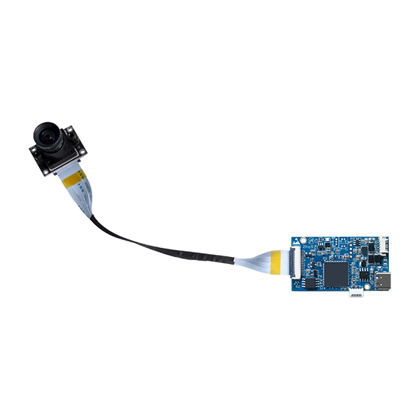
Matching sensor capabilities to your operational environment guarantees optimal performance. Application-driven specifications must dictate your hardware choices. For instance, select a 4MP/8MP Starlight Full-Color USB Camera Module for environments requiring superior dynamic range. This component ensures clear low-light visibility. It achieves this without relying on external infrared illumination. High dynamic range stops bright lights from washing out crucial scene details.
Conversely, specify a 4K/60P Zoom Camera Module for applications demanding high-framerate fluid motion. Such components provide pristine optical clarity. They vastly improve modern Video Conference setups. They also elevate interactive Distance Education podiums. Fast framerates prevent motion blur when subjects move quickly across the frame.
Beyond optical performance, verify the physical form factor and strict thermal constraints. Check the Z-height and PCB footprint carefully. Compare the thermal dissipation limits of the replacement part against your host device housing. A sensor running too hot degrades image quality rapidly. Heat introduces visual artifacts known as thermal noise. Ensure your new component fits precisely inside the existing thermal envelope.
You must also ensure the chosen unit meets relevant compliance and reliability standards. This includes stringent sterilization tolerances for Medical Devices. Diagnostic Medical Detection equipment requires absolute pixel accuracy. Industrial scenarios demand robust builds. A factory floor Robot experiences constant vibration. Your replacement optics must withstand these intense mechanical shocks without losing focal alignment.
Common Mistake: Ignoring the interface protocol. A MIPI CSI-2 sensor will never communicate across a standard USB controller. You need a dedicated bridge chip.
| Application Focus | Recommended Resolution | Ideal Interface Protocol | Key Performance Metric |
|---|---|---|---|
| Low-Light Monitoring | 4MP / 8MP Starlight | USB 3.0 / MIPI | High Signal-to-Noise Ratio (SNR) |
| High-Speed Motion | 4K at 60 FPS | MIPI CSI-2 / DVP | Minimal Motion Blur |
| Harsh Environments | Variable (1080p to 4K) | FPD-Link III / GMSL | Vibration and Thermal Resistance |
Thorough preparation prevents costly hardware damage. Establish strong ESD safety protocols before opening any electronic device. Set up a static-free workspace utilizing grounded silicone mats. Always wear appropriately tested anti-static wrist straps. This protects bare PCB components from sudden voltage spikes. It also shields the highly sensitive image signal processor (ISP) from invisible static discharges. Even a tiny static shock destroys microscopic traces instantly.
Assemble the correct tooling requirements before you begin. Gather non-conductive plastic spudgers. Organize precision bit sets including Torx and Phillips drivers. Keep precision ceramic tweezers nearby. Avoid metal pry tools entirely. Metal tools easily scratch logic boards. They can short out exposed power traces and ruin expensive motherboards.
Power isolation remains absolutely non-negotiable. Disconnect all main alternating current power supplies. For battery-operated hardware, physically detach the internal battery connector. Discharge residual board capacitance safely. Hold the main power button down for ten seconds before touching the sensor housing. This bleeds off trapped electrical energy safely.
Finally, prioritize detailed workspace documentation. Photograph the original cable routing pathways. Document all specific screw placements clearly. Hardware tolerances in modern devices are exceptionally tight. Incorrect reassembly can easily pinch delicate ribbon cables. It can also compromise crucial weather seals. Take reference photos at every single disassembly stage.
ESD Protection: Grounded mat and tested wrist strap equipped properly.
Tooling: Plastic spudgers, tweezers, and precision screwdrivers staged.
Power Isolation: Main power detached; internal capacitance discharged fully.
Documentation: Camera ready for sequential step-by-step disassembly photos.
Workspace Lighting: High-CRI LED task lighting positioned above the workbench.
Precision is paramount during physical disassembly. Follow these exact stages carefully. You must protect both the host device and your new replacement components.
Accessing the Component: Carefully remove outer plastic housings. Detach any internal thermal shields. Retain and organize all specific screw lengths on a magnetic mat. Placing a long screw into a short internal standoff risks puncturing the underlying motherboard during reassembly.
Disconnecting the Defective Module: Locate the specific ZIF (zero-insertion-force) or snap-fit connector. This secures the camera module to the logic board. Gently flip up the fragile locking mechanism using a plastic spudger. Slide the ribbon cable out horizontally. Never pull vertically on an FPC cable. Vertical pulling tears the fragile copper traces instantly.
Extracting and Cleaning: Remove the old sensor carefully. Manufacturers often adhere these parts using thermal tape or adhesive gaskets. Apply minimal, highly controlled heat from a hot air station. This softens the bond safely. Clean the bare mounting bracket of any residual adhesive. Use high-purity isopropyl alcohol and a lint-free swab.
Installing the Replacement: Seat the new unit flush against the factory alignment pins. Route the delicate FPC cable precisely along its original path. Seat the cable fully into the connector housing. Engage the locking latch firmly. Ensure the printed alignment line on the cable sits completely parallel beside the connector housing.
Restoring Environmental Seals: Reapply any necessary ingress protection (IP) gaskets. Install fresh thermal pads if required. This step remains critical for maintaining operational integrity. Outdoor or submerged hardware depends entirely on flawless seals to prevent liquid ingress.
What to watch out for: Always double-check your connector seating. A slightly misaligned FPC cable causes power shorts. It often results in a completely blank video feed upon system boot.
Hardware seating marks only the halfway point of the repair. Thorough software validation guarantees operational success. Conduct an initial Power-On Self Test (POST) before sealing the outer chassis fully. Boot the host device. Verify the operating system detects the new hardware immediately. It should not throw any driver error codes. If the system fails to recognize the component, check your cable connections immediately.
Next, perform strict optical calibration. Utilize standard diagnostic test charts, like the ISO 12233 resolution chart. Evaluate the generated image carefully. Check for crisp edge-to-edge sharpness. Verify the correct focal length across the entire field of view. Confirm the absolute absence of sensor dust or internal lens debris. Even microscopic dust particles ruin high-resolution image outputs.
Proceed to rigorous stress testing protocols. Run the device at its maximum resolution and highest framerate for an extended period. A two-hour burn-in test usually suffices. This validates thermal stability. It ensures zero frame dropping occurs under heavy processing loads. Monitor the ISP temperature carefully during this phase.
Finish with final assembly and detailed documentation. Once you validate system performance completely, seal the chassis. Torque all exterior screws to manufacturer specifications. Update internal maintenance logs. Record the new serial number and current firmware version. This creates a reliable audit trail for future maintenance cycles.
| Testing Phase | Expected Optimal Output | Common Fault Indicator | Required Corrective Action |
|---|---|---|---|
| Initial POST | Device OS registers hardware ID instantly | "No Device Found" error or black screen | Power down, reseat the FPC cable, and verify latch closure |
| Optical Calibration | Sharp focus across the entire test chart | Blurry edges, distorted lines, or visible dark spots | Adjust focal ring mechanically, clean lens using a microfiber swab |
| Stress Testing | Stable framerate, normal operating temperatures | Thermal throttling, visual artifacting, or dropped frames | Check thermal pad application, ensure heat sink contact is flush |
Executing a successful hardware replacement requires transitioning smoothly from physical safety to precise software validation. By carefully matching specifications to your environment, you maximize device longevity. Whether you prioritize high framerates or specialized low-light sensitivity, the right hardware transforms system performance. Follow these actionable next steps to guarantee lasting reliability:
Strictly adhere to standardized teardown SOPs to minimize operational downtime and prevent accidental connector damage.
Prioritize extensive post-installation calibration to guarantee optimal optical clarity and stable thermal performance.
Audit your current systems today to identify underperforming sensors before they fail entirely.
Build a dedicated in-house replacement kit equipped with proper ESD tools and ISO testing charts.
Always source your replacement parts exclusively from vetted suppliers capable of providing comprehensive datasheet documentation and firmware support.
Proper preparation guarantees your hardware remains field-ready. Equip your team with the right knowledge, and hardware maintenance becomes a predictable, manageable process rather than an operational crisis.
A: In most commercial and industrial hardware, unauthorized disassembly voids the original OEM warranty immediately. Always check your service level agreement (SLA) before breaking factory security seals. Consult your hardware provider if your team lacks certified internal maintenance training.
A: If you install an identical part number, standard plug-and-play rules usually apply. However, upgrading to a different specification requires intervention. Higher resolutions typically require new drivers or ISP firmware updates. This ensures the host board processes the increased data rate correctly without bottlenecking the entire system.
A: Improperly seated FPC cables usually cause this issue. A torn internal trace in the ribbon also triggers glitches. Sometimes, a mismatch in the interface protocol occurs. Attempting to run a MIPI CSI-2 sensor on a board configured for a different lane count will fail. Verify physical connections first.


