
English
English
Views: 0 Author: Site Editor Publish Time: 2026-09-30 Origin: Site


Selecting a high-performance optical block represents only the first step in modern imaging design. Engineers constantly face a major hardware hurdle. You must successfully route raw video output to standard displays or central processing units. This gap frequently halts production timelines. Standard block cameras utilize raw LVDS outputs. They do this to ensure zero-latency, uncompressed transmission inside compact enclosures. However, downstream systems like field monitors, single board computers, and capture cards demand HDMI or MIPI CSI-2 inputs. You cannot connect them directly.
This guide solves that integration bottleneck. We provide system architects and integration engineers a transparent, vendor-neutral framework. You will learn to evaluate, select, and implement LVDS-to-HDMI interface solutions for compact camera modules. We cover physical constraints, thermal limitations, and control protocol requirements. By the end, you will know exactly how to finalize your video ingestion strategy effectively.
Native LVDS provides zero-latency raw transmission but requires custom PCB design or third-party interface boards for standard HDMI output.
Selecting the right interface board (e.g., for the Tamron MP3010M-EV) requires balancing SWaP (Size, Weight, and Power) constraints with thermal management.
Integration into SBCs (like Raspberry Pi 5) or industrial systems introduces specific VISCA communication and MIPI CSI-2 conversion hurdles that must be planned for in the prototyping phase.
Off-the-shelf LVDS-to-HDMI conversion boards reduce time-to-market but require strict EMI/EMC compliance evaluation for medical and aerospace applications.
Many OEMs specify compact block cameras because they offer superior optics. They also provide reliable optical image stabilization (OIS). However, teams often face severe production delays. Translating complex video outputs into standard formats creates unexpected roadblocks. Direct connections fail without proper signal processing. You need a robust strategy to handle this conversion.
Engineering teams often underestimate the video translation phase. You might choose a premium Tamron 10X Optical Zoom Camera for its pristine glass and autofocus speed. Yet, the raw 30-pin KEL output remains unusable to generic HDMI monitors. Custom engineering takes months. Software teams wait idly for video feeds. This translates directly to delayed product launches and lost market opportunities.
A successful interface architecture must pass several strict tests. First, it must maintain perfect 1080p60 signal integrity. Drops in frame rate or color fidelity ruin the optical block's value. Second, the converter must introduce only sub-frame latency. Surgical displays and drone gimbals require real-time feedback. Finally, the board must fit within your designated physical footprint. Space remains extremely tight inside UAV payloads, surgical lights, and remotely operated vehicles (ROVs).
Low-Voltage Differential Signaling (LVDS) serves as the industry standard for internal camera data. It transmits high-speed video data over twisted wire pairs. This approach minimizes electromagnetic interference. The 30-pin KEL connector carries these differential pairs alongside power and control signals. However, generic displays speak TMDS (Transition Minimized Differential Signaling) via HDMI. Direct physical connection remains fundamentally impossible. You must introduce an active signal processing IC to bridge this gap.
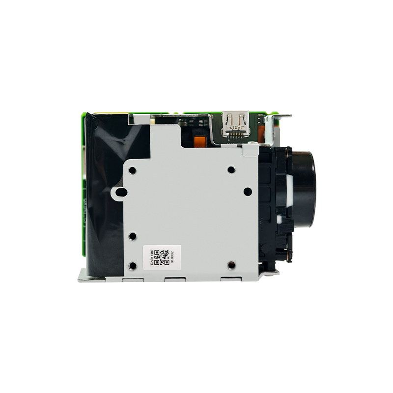
We can categorize interface strategies into three distinct approaches. You must weigh development speed against physical customization. Each approach carries unique technical trade-offs.
Developing a proprietary board gives you ultimate control. Hardware engineers can strip away unnecessary connectors. They design the exact form factor required for your specific housing.
Pros: You dictate the exact dimensions and power delivery methods. It yields the lowest per-unit cost during high-volume manufacturing. You avoid paying margins to third-party interface vendors.
Cons: Upfront Non-Recurring Engineering (NRE) costs run high. R&D timelines extend by several months. Your internal team bears the full burden of EMI/EMC compliance testing and signal integrity validation.
Specialized interface companies manufacture ready-to-use boards. You simply connect the micro-coaxial cable and power it up.
Pros: These solutions allow immediate deployment. Signal integrity comes pre-verified by experts. They often feature native VISCA control breakout ports for easy serial communication.
Cons: The physical dimensions remain fixed. The pre-designed rectangular boards might not suit ultra-compact cylindrical housings. They also carry a premium per-unit cost compared to custom high-volume boards.
Modern systems often bypass traditional HDMI monitors entirely. Instead, they route video straight into a compute module. You utilize bridge boards to convert LVDS into MIPI CSI-2 streams. Popular host platforms include the Raspberry Pi 5 and NVIDIA Jetson series.
Implementation: You attach a specialized HAT or carrier board adapter. The adapter decodes the LVDS stream and feeds it directly into the processor's image pipeline.
Best For: Edge AI processing thrives on this method. Computer vision applications and smart surveillance prefer direct compute ingestion. It eliminates the latency of rendering HDMI video before software analysis. Using a Tamron Full HD Zoom Camera this way unlocks powerful automated tracking capabilities.
Selecting the right conversion strategy involves deep technical vetting. You must look beyond simple video output. Environmental and electrical factors dictate long-term system reliability.
Every added gram affects drone flight times. You must calculate how the interface board alters the overall payload footprint. The ultra-compact Tamron MP3010M-EV Zoom Camera measures extremely small on its own. Bolting a generic, oversized HDMI board to its back defeats the purpose of choosing a micro-block camera. Check the board's power draw. Ensure your primary battery or power supply can handle both the camera motors and the conversion IC.
Active video conversion requires significant processing power. HDMI conversion chips generate substantial heat during 1080p60 translation. You must model the thermal environment. Sealed enclosures trap this heat. Assess whether the chosen board requires active fan cooling. In many industrial applications, passive thermal pads linking the board to an aluminum outer chassis suffice. Overheating leads to dropped frames or complete video failure.
A zoom camera loses its utility without active lens control. The interface board must reliably pass VISCA commands. Ensure it supports your chosen physical layer, whether RS-232, RS-485, or TTL UART.
Best Practice: Verify that the board isolates the communication lines from electrical noise. You need uninterrupted control over zoom, focus, and OIS functions without annoying communication latency.
Medical and aerospace applications mandate strict regulatory adherence. You must evaluate EMI/EMC emissions carefully. Poorly shielded interface boards leak radio frequencies. This interference disrupts nearby GPS modules or sensitive patient monitoring equipment. IEC 60601 compliance for medical deployments requires heavy shielding and strict power isolation. Do not assume a commercial prototype board passes medical-grade emission tests automatically.
Even with the perfect board selected, assembly introduces severe risks. Hardware engineers encounter several common pitfalls during the physical integration phase.
Routing 30-pin KEL micro-coaxial cables demands extreme care. These wires are incredibly thin and fragile. Mishandling them causes immediate signal attenuation. Pan-tilt-zoom (PTZ) applications introduce repeated bending. Constant motion leads to physical cable fatigue and eventual internal wire breakage.
Common Mistake: Forcing a micro-coaxial cable into a tight 90-degree bend inside a gimbal housing. Always adhere to the manufacturer's specified minimum bend radius to prevent impedance mismatches.
Improper voltage application destroys hardware instantly. Block cameras typically expect a regulated 5V DC input. However, many standard HDMI interface boards require 9V to 12V inputs. If you mix up the voltage rails, you risk frying the camera block entirely. Always verify power pinouts before connecting the battery. Some custom interface boards feed power backward to the camera. Ensure the power sequencing starts the board and the camera in the correct, synchronized order.
Sometimes you power everything up, but the screen remains completely blank. This usually points to an EDID (Extended Display Identification Data) handshake failure. The camera might output a rigid 1080p60 signal. If the HDMI receiver board incorrectly negotiates with a 1080i or 720p monitor, the video link fails. Troubleshooting requires forcing specific resolutions via VISCA commands. You must match the camera's internal register settings perfectly to the display's capabilities.
Engineering teams need a clear path forward. We organized a decision matrix to help you choose the correct integration path.
Interface Solution Decision Matrix
| Application Scenario | Recommended Approach | Primary Advantage |
|---|---|---|
| Rapid Prototyping & Standard Enclosures | COTS LVDS-to-HDMI Evaluation Kit | Immediate plug-and-play video testing |
| Edge AI & Computer Vision Systems | LVDS-to-MIPI CSI-2 Bridge Board | Direct compute ingestion for software processing |
| Ultra-Lightweight UAV Payloads | Custom In-House PCB Design | Absolute minimum gram weight and physical size |
Do not commit to high-volume manufacturing blindly. You must validate the hardware in real-world conditions first. Request CAD models, specifically STEP files, from the interface board manufacturer. Import these into your mechanical assembly software to check clearances.
Next, scrutinize the electrical datasheet. Verify pin-out compatibility between the board and your specific camera model. Remember that while connectors look identical, power pin locations vary. Finally, order a single developer evaluation kit. Test it thoroughly using a Tamron Full HD Zoom Camera. Confirm heat dissipation and control passthrough before placing bulk orders.
The true value of a premium camera module is only realized when its video output integrates flawlessly into your broader system. An isolated camera block provides no operational value. You must bridge the LVDS gap successfully.
We advise engineering teams to finalize their video ingestion method early. Decide between direct display or compute ingestion before locking in your hardware dimensions. Making this choice late forces painful mechanical redesigns. Follow these critical steps:
Evaluate SWaP and thermal limits immediately during the draft phase.
Validate VISCA control passthrough alongside standard video signals.
Map out power sequencing carefully to prevent permanent hardware damage.
Consult with an integration specialist early in your project phase. Request detailed mechanical and electrical data sheets for all recommended interface boards. Taking these deliberate steps ensures a smooth, reliable product launch.
A: High-quality hardware converters introduce negligible latency (typically less than a few microseconds, well under a single frame), but the display monitor itself may add processing lag.
A: No. HDMI carries the video signal. Camera control requires routing serial communication (VISCA protocol) via Rx/Tx pins, which most interface boards break out into a separate terminal.
A: While the 30-pin KEL connector is an industry standard, specific pin definitions (like power, reset, and serial lines) can vary slightly between manufacturers. Always verify the exact datasheet for the specific Tamron model before powering up an unverified board.


