English
English


1/2.3-inch CMOS
1/2.3-inch CMOS
1/2.3-inch CMOS
1/2.3-inch CMOS
1/2.3-inch CMOS
1/2.3-inch CMOS
1/2.3-inch CMOS
1/2.3-inch CMOS
1/2.3-inch CMOS
1/2.3-inch CMOS
1/2.3-inch CMOS
1/2.3-inch CMOS
1/2.3-inch CMOS
1/2.3-inch CMOS
1/2.3-inch CMOS
1/2.3-inch CMOS
1/2.3-inch CMOS


This interface board is an integrated solution tailor-made for the full range of Sony FCB digital HD camera modules. Via seamless LVDS interface connection with the camera module, it supports simultaneous output of four video signals: 3G-SDI, LVDS loop-out and CVBS. It offers users flexible and diverse video output options to meet video transmission requirements for various application scenarios.
For signal processing, the board delivers robust auto-recognition performance. It accurately identifies HD signals without requiring any configuration on the camera module, ensuring stable and high-quality video output.
In terms of control functions, it supports RS-485 control and features a Chinese-English bilingual OSD menu for simple, intuitive operation. Users can easily perform basic functions such as zoom and focus via physical buttons, significantly improving usability. In addition, it automatically recognizes PELCO-D/P protocols for broader compatibility with different control systems.
Notably, it also supports third-party camera modules compliant with the Sony VISCA protocol, offering a cost-effective solution for diverse user needs.
• Plug-and-Play HD Access: Connect the Sony FCB HD camera module via LVDS and RF cables with power supply connected. No additional configuration is required; the device automatically identifies the module and outputs clear HD-SDI signals, enabling true plug-and-play functionality.
• Flexible Parameter Configuration: The OSD menu is accessible via physical buttons, RS-485 control keyboard or decoder board, enabling users to conveniently adjust the module's technical parameters. All configured parameters are automatically saved.
• Multi-Format Simultaneous Output: Supports concurrent output of 3G-SDI,LVDS loop-out and CVBS signals, allowing on-site camera positioning and parameter debugging using an engineering tester (pattern generator).
• Standard Serial Control: Features RS-485 communication with auto-recognition of PELCO-D/P protocols. Baud rates of 2400/4800/9600 bps are selectable, with address configuration ranging from 1 to 255.
• Power-Off Parameter Retention: All saved parameters are retained upon power loss. No re-configuration is required after restart,improving operational efficiency.
• Optional RS-232 Communication Interface: An optional RS-232 interface is provided for communication with PCs or MCUs,expanding application scenarios.
• Safe Video Format Switching (Optional): Equipped with an emergency video format function. In case of image loss, the output can be switched to 720P50, 1080I50 or CVBS; remote switching via RS-485 control keyboard is also supported.
• Optional Presets & Auto Cruise (Optional): Provides 10 user-defined preset positions and an optional auto-cruise function. Cruise dwell time is adjustable from 5 to 999 seconds for improved monitoring coverage and efficiency.
Brand | Model | Supported SDI Video Formats |
Sony | FCB-EV9520L | 1080P60, 1080P59.94, 1080P50, 1080P30, 1080P29.97, 1080P25 1080I60, 1080I59.94, 1080I50 720P60, 720P59.94, 720P50, 720P30, 720P29.97, 720P25 |
FCB-EV9500L | ||
FCB-EV7520A/FCB-CV7520A | ||
FCB-EV7520/FCB-CV7520 | ||
FCB-EV7100/FCB-CV7100 | ||
FCB-EH6300/FCB-CH6300 | 1080P30, 1080P29.97, 720P60, 720P59.94, 720P50, 720P30, 720P29.97, 720P25 | |
Volers | VRS-HD5101 | 1080P60, 1080P50, 1080P30, 1080P25 720P60, 720P50, 720P30, 720P25 |
VRS-HD5201 | ||
VRS-HD5301 | ||
VRS-HD5363 | ||
VRS-HD5365 | ||
Tamron | MP3010M-EV |
*Note: Compatible with most third-party full-HD cameras supporting the Sony VISCA protocol.
Video Output Format | Simultaneous output of 3G-SDI, LVDS loop-out, and CVBS | Communication Protocol | RS-485 (standard), RS-232 (optional), TTL-232 (optional) |
PELCO Protocol | Auto identify PELCO-D, PELCO-P protocol | Video Format | 1080P, 1080I, 720P |
Operating Temperature | -5~65°C ( 23°F~149°F) | Power Supply | DC12V 1A |
Weight | Approx. 22g (Approx. 0.78oz) | Dimensions | Approx. 42*42*19mm |
Number | Type | Function |
F1 | Molex Connector: 532610671 (1.25MM pitch 6Pin Socket) | Interface definition is shown in table F1-1 |
F2 | Molex Connector: 532610871 (1.25MM pitch 8Pin Socket) | Interface definition is shown in table F2-1 |
F3 | FPC connector | Connect the two boards together with wires |
F4 | LVDS Loop-out | Signal loop-out interface |
F5 | LVDS Input | Input interface, connected to the camera's LVDS interface |
F6 | 5-way Switch | Integrates focus adjustment, zoom control, and menu access functions |
F7 | SDI Interface | SDI Output |
|
|
|
| Board A Front Side | Board A Back Side | Board B Front Side |
Table: F1-1 | |||
1 | GND | 4 | Focus Near |
2 | Menu | 5 | Zoom Out |
3 | Focus Far | 6 | Zoom In |
Table: F1-1 | |||
1 | CVBS | 5 | TX |
2 | GND | 6 | RX |
3 | GND(DC12V-) | 7 | RS 485+ |
4 | DC12V+ | 8 | RS 485- |
Model No. | Communication Method |
PCB-HD401 | With RS-485 control |
PCB-HD402 | With RS-485 & RS-232 control |
PCB-HD403 | With RS-485 & TTL-232 control |
| PCB-HD404 | With preset position |
| PCB-HD405 | With RS-232 control and preset position |
| PCB-HD406 | With TTL-232 control and preset position |
|
|
|
| 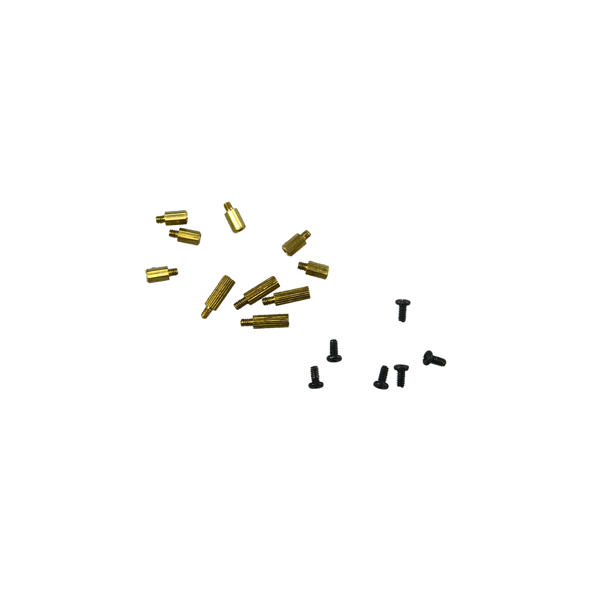 | 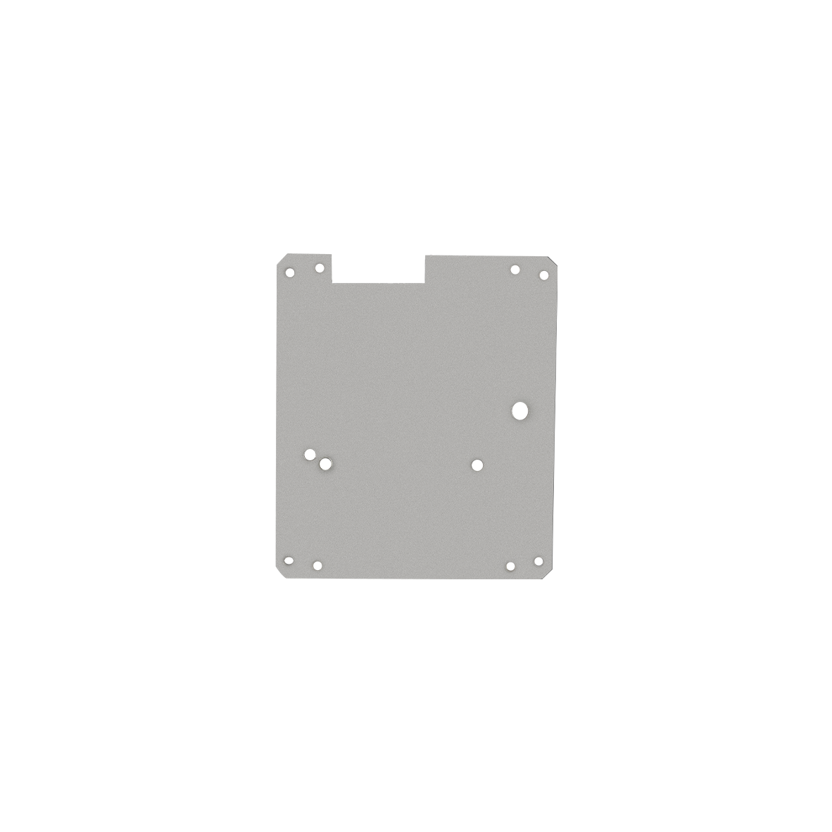 |
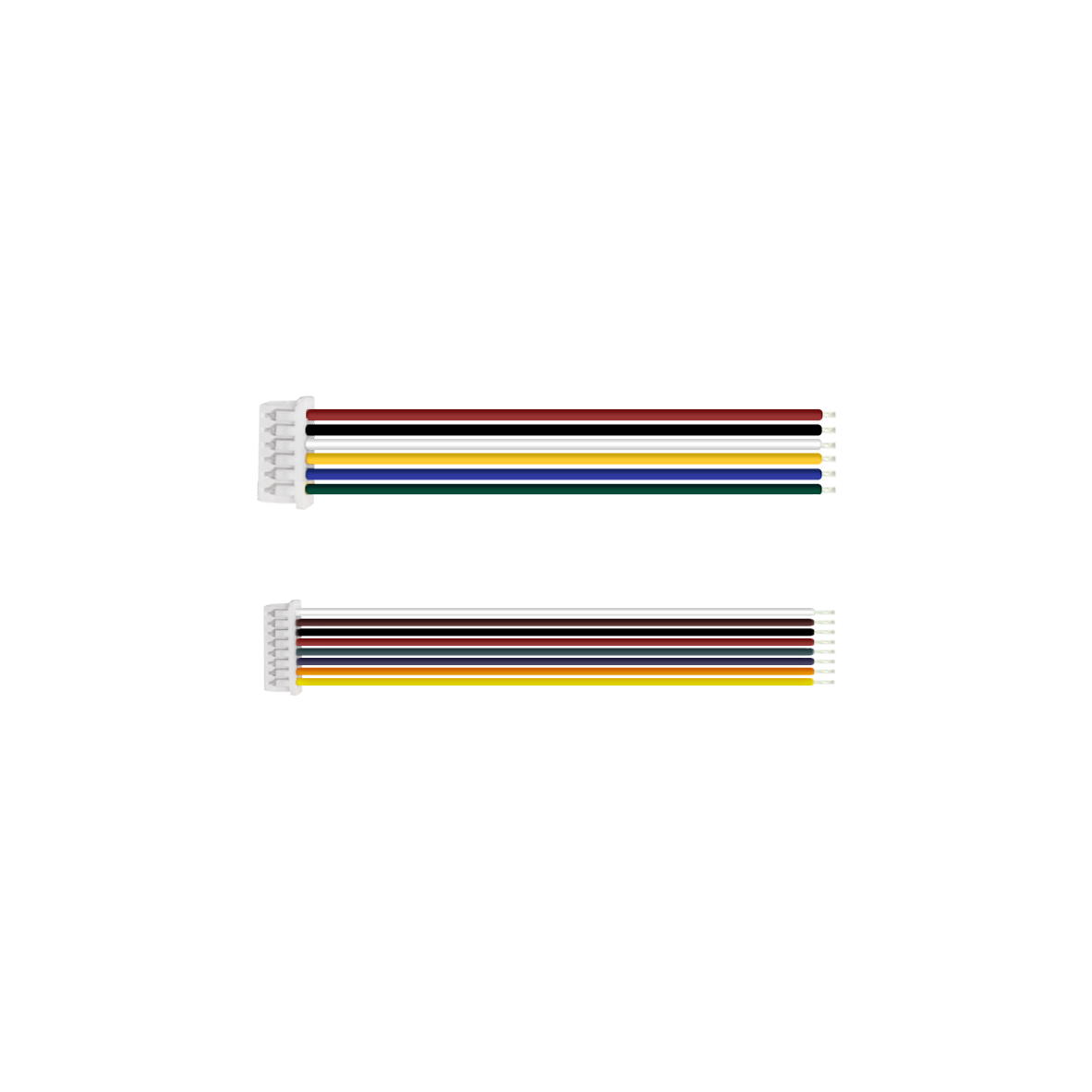
LVDS Coaxial Cable (80mm), Customizable Length (Optional) | 6-Pin Terminal Wire (150MM) (Standard) | 8-Pin Terminal Wire (150MM) (Standard) | PFC Cable (60MM) (Standard) | Screw/Copper pillar: M2*5 (Optional) | Iron Plate(50*50mm) (Optional) |
 |  |  |
a. Interface board assembled with Sony Block camera FCB-EV9520L | b. Interface board assembled with Sony Block camera FCB-EV9500L | c. Interface board assembled with Sony Block camera FCB-EV7520 |
*Note:The product supports individual purchase or "block camera+interface board" package purchase. The whole set comes without pre-installation by default. Specify installation needs when ordering.
Preparation
|
|
|
|
|  |
Exemplified by FCB-EV9520L | 30pin micro coaxial cable | 6/8Pin Terminal Wire | Screw/Copper pillars | Iron Plate | PFC Cable |
Connection Steps
|
|
|
StepⅠ: 1. Physically remove the screws and stand-offs from the mini 3--in--1 interface board (as shown in ① above). | Step Ⅱ: 2. Mount the metal plate onto the rear side of the camera and fasten the screws (as shown in Figure ② above). 3. Install the four stand-offs onto the metal plate (as shown in Figure ③ above). | Step Ⅲ: 4.Connect the LVDS coaxial cable in parallel to the camera module (as shown in Figure ④ above). 5. Connect the other end of the LVDS coaxial cable in parallel to Board A of the mini 3-n-1 interface board (as shown in Figure ⑤ above). Note: Keep the gold contact pins facing upward. Reverse insertion is strictly prohibited. |
 |  |  |
Step Ⅳ: 6. Mount Board A of the mini 3-in-1 interface board onto the rear of the camera (as shown in Figure ⑥ above). | Step Ⅴ: 7. Physically connect Board A and Board B with the forward-type 50-pin FPC cable (as shown in Figure ⑦ above). Notes: Standard pre-installed cable length: 6-10cm. Max recommended length ≤15cm; longer cables may impair signal transmission. | Step Ⅵ 8. Install the Board B onto the Board A, and tighten the screws (as shown in Figure ⑧ above) |
 |  | |
Step Ⅶ 9. Physically connect the 6-pin terminal wire to the mini interface board (as shown in Figure ⑨ above). | Step Ⅷ 10. Physically connect the power cable to the mini interface board (as shown in Figure ⑩ above). |
Thank you very much for purchasing our company's products. If you have any questions, please feel free to contact us.
The photos and actual objects depicted in this Manual are provided solely for reference and guidance to users.
We do not guarantee that they are completely identical to the actual products. Please refer to the actual products.
Design, features and specifications are subject to change without notice.
| Image | Product Name |
|---|---|
 | PCB-HD201 SDI/CVBS/HDMI-Compatible 3-in-1 Multi-functional Interface Board |