English
English


1/2.3-inch CMOS
1/2.3-inch CMOS
1/2.3-inch CMOS
1/2.3-inch CMOS
1/2.3-inch CMOS
1/2.3-inch CMOS
1/2.3-inch CMOS
1/2.3-inch CMOS
1/2.3-inch CMOS
1/2.3-inch CMOS
1/2.3-inch CMOS
1/2.3-inch CMOS
1/2.3-inch CMOS
1/2.3-inch CMOS
1/2.3-inch CMOS
1/2.3-inch CMOS
1/2.3-inch CMOS


3G-SDI Interface Board is specifically designed for the entire series of Sony FCB high-definition block cameras. It incorporates advanced LVDS interface technology, enabling easy connection to camera modules. Once connected, the interface board can automatically identify the camera's model and automatically output the appropriate high-definition video format, ensuring that the video signal remains stable and high-definition throughout.
In terms of compatibility, this interface board excels. Not only is it applicable to Sony FCB series modules, but it also supports other brand modules that comply with the Sony VISCA protocol. This means that whether you are using Sony camera blocks or cameras from other compati-ble brands, this interface board board can provide you with stable and efficient control and signal output solutions.
Through such a design, we aim to create a convenient, efficient, and professional 3G-SDI interface board for users, fully meeting the application needs of high-definition camera blocks in various scenarios.
•Hardware Configuration:
Dual 4-layer military-grade PCB board with gold-plated surface for easy soldering and joint protection.
Customized 75-ohm pure copper MCX connectors, ARM processors, UNI-ROYAL capacitors/resistors, and other quality components ensure HD-SDI signals pass eye pattern test.
Overseas-imported chips, UNI-ROYAL capacitors/resistors, and other components also enable HD-SDI signals to pass the test.
•Connection and Recognition:
Connects to Sony FCB HD block camera via 30-pin LVDS cable. Automatically recognizes and displays HD-SDI signals without camera settings.
Supports OSD menu via buttons, 485 control keyboard, or decoder for setting and saving camera parameters.
•Signal Output:
Supports HD-SDI output for precise camera position adjustment at site and easy parameter setting, improving debugging efficiency.
•Control and Communication:
Supports RS485 control, recognizes PELCO-D/P protocols. Baud rate settable to 2400/4800/9600bps, address range 1-255.
Supports TTL232 control (optional) for computer/MCU communication.
•Special Functions:
Power-off memory: no need to reset camera parameters after power loss.
Video format change: switch to 720P50, 1080I50, or CVBS when image not visible; remote change via RS-485 keyboard.
10 preset positions and automatic touring (5-999s, optional).
Optional auxiliary switch for wiper and external device control.
•Compatibility and Application Fields:
Compatible with non-Sony block cameras supporting Sony VISCA protocol.
Applied in security, intelligent transport, unmanned flight equipment, photo booths, police cars, night vision devices, and video conferences.
Brand | Model | 3G-SDI | HD-SDI | CVBS |
Sony | FCB-EV9520L | 1080P60,1080P59.94, 1080P50, 1080P30, 1080P29.97, 1080P25, 1080P20, 720P60, 720P59.94, 720P50 720P30, 720P29.97, 720P25 | 1080P60, 1080P59.94, 1080P50 1080P30, 1080P29.97, 1080P25 1080I60, 1080I50 720P60, 720P59.94, 720P50 720P30, 720P29.97, 720P25 | Not supported |
FCB-EV9500L | ||||
FCB-EV7520A | ||||
FCB-EV7520 | PAL,NTSC (Can't sync with HD output) | |||
FCB-EV7100 | ||||
FCB-EH6300 | 720P60, 720P59.94, 720P50 720P30, 720P29.97, 720P25 | |||
Volers | VRS-HD5101 | 1080P60, 1080P50 | 1080P60, 1080P50, 1080P30, 1080P25, 1080I60, 1080I50 720P60,720P50,720P30,720P25 | Not supported |
VRS-HD5201 | ||||
VRS-HD5301 | ||||
VRS-HD5363 | ||||
VRS-HD5365 | ||||
Tamron | MP3010M-EV | |||
*Note: This product works with Sony's FCB HD cameras and other compatible camera blocks supporting Sony's Visca-command.
Compatible Block Cameras | Sony FCB HD series, non-Sony cameras compatible with Sony-Visca command. | Video Output Format | 1080P、1080I、720P |
Communication Control Protocol | Communication Control Protocol | Operating Temperature | -20~65°C |
Communication Interface Control | RS-485 (optional), TTL-232 (optional) | Power Supply to Camera | Supported (requires external power supply) |
RF Interface | MCX | Power Supply | DC12V 1A |
Product Net Weight | Approx 12g | Product Dimensions | Approximately 42*42*5mm (MCX connector height: 7.5mm) |
F1. MCX video connector: Serves as an HD-SDI/3G-SDI high-definition video output interface for stably outputting high-definition video signals.
F2. External synchronization: Transmits synchronization signals to the external gen-lock input port of the camera to achieve synchronization.
F3. Internal synchronization: Completes corresponding operations based on the synchronization signals generated by the internal synchronization signal generation circuit within the camera.
Note: Internal and external synchronization modes are only applicable to the Sony FCB-EH/CH series.
F4. Molex connector (532610671): Uses a 6Pin connector with a 1.25MM pitch. The interface definition is shown in Table F4-1.
F5. Molex connector (532610871): Uses an 8Pin connector with a 1.25MM pitch. The interface definition is shown in Table F5-1.
F6. Fuse: Provides 1.2A overcurrent protection to effectively protect the camera and prevent camera damage due to overcurrent.
F7. LVDS connector: Used for connecting to the LVDS interface of the camera to achieve stable connection and signal transmission.
 Front of the board
  Rear of the board
 Table: F4-1 | |||
1 | Zoom in | 4 | Focus down close |
2 | Zoom out | 5 | Menu |
3 | Focus down close | 6 | Ground |
Table: F5-1 | |||
1 | RS485 - | 5 | DC12V + |
2 | RS485 + | 6 | DC12V - |
3 | RX Transmission | 7 | CVBS- |
4 | TX Transmission | 8 | CVBS+ |
Model No. | Communication Method |
PCB-HD014 | With TTL-232 control |
PCB-HD015 | Special program for medical shadowless lamp |
PCB-HD020 | With RS-485 control |
PCB-HD022 | With RS-485& TTL-232 control |
PCB-HD023 | Drone with data communication |
PCB-HD024 | Special for shadowless lamp (with wireless remote control, receiver, 5M RF cable) |
|
|
|
|  |  |
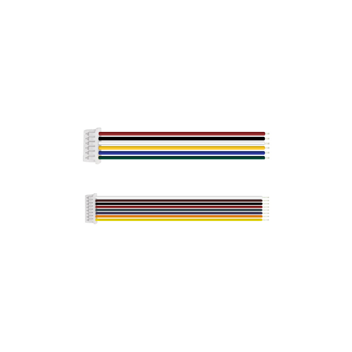
LVDS Coaxial Cable (8cm), Customizable Length (Optional) | RF coaxial cable assembly(210MM) Customizable Lengt(Optional) | 6-Pin Terminal Wire (15mm) (Standard) | 8-Pin Terminal Wire (15cm) (Standard) | Screw/Copper pillar: M2*5 (Optional) | Iron Plate(50*50mm) (Optional) |
 |  |  |
a. Interface board assembled with Sony Block camera FCB-EV9520L | b. Interface board assembled with Sony Block camera FCB-EV9500L | c. Interface board assembled with Sony Block camera FCB-EV7520 |
*Note: The product supports individual purchase or "block camera+interface board" package purchase. The whole set comes without pre-installation by default. Specify installation needs when ordering.
Preparation
|
|
|
|
|  |
FCB-EV9520L | 30Pin LVDS Coaxial Cable | RF coaxial cable assembly | 6/8Pin Terminal Wire | Screw/Copper pillars | Iron Plate |
Connection Steps
Physical Assembly Steps Only (No Electrical Work)
Notes: The steps demonstrate physical connection only-electrical connection is excluded. No image output at this stage. For electrical connection assistance, contact technical support.
|
|
|
StepⅠ: 1. Install four copper pillars onto the iron plate (as shown in Figure ① above). 2. Install the iron plate onto the rear of the camera and tighten the screws (as shown in Figure ② above). | StepⅡ: 3. Connect one terminal of the LVDS coaxial cable to the HD block camera (as shown in Figure ③ above). 4. Connect the other terminal of the LVDS coaxial cable to the 3G-SDI interface board (as shown in Figure ④ above). Note: Plug in the LVDS coaxial cable with gold-plated pins on connectors facing up. Reverse insertion is strictly prohibited. | Step Ⅲ: 5. Install the 3G-SDI interface board to the rear of the camera and tighten the screws (as shown in Figure ⑤ above). |
 |  |  |
Step Ⅳ: 6. Physically connect the 8-pin terminal wire to the 3G-SDI interface board (as shown in Figure⑥ above). | Step Ⅴ: 7. Physically connect the power cable to the 3G-SDI interface board (as shown in Figure ⑦ above). | Step Ⅵ 8. Connect the MCX male connector to the 3G-SDI interface board (as shown in figure ⑧ above) |
Thank you very much for purchasing our company's products. If you have any questions, please feel free to contact us.
The photos and actual objects depicted in this Manual are provided solely for reference and guidance to users.
We do not guarantee that they are completely identical to the actual products. Please refer to the actual products.
Design, features and specifications are subject to change without notice.
| Image | Product Name |
|---|---|
 | VRS-UD601 12G-SDI Interface Board |